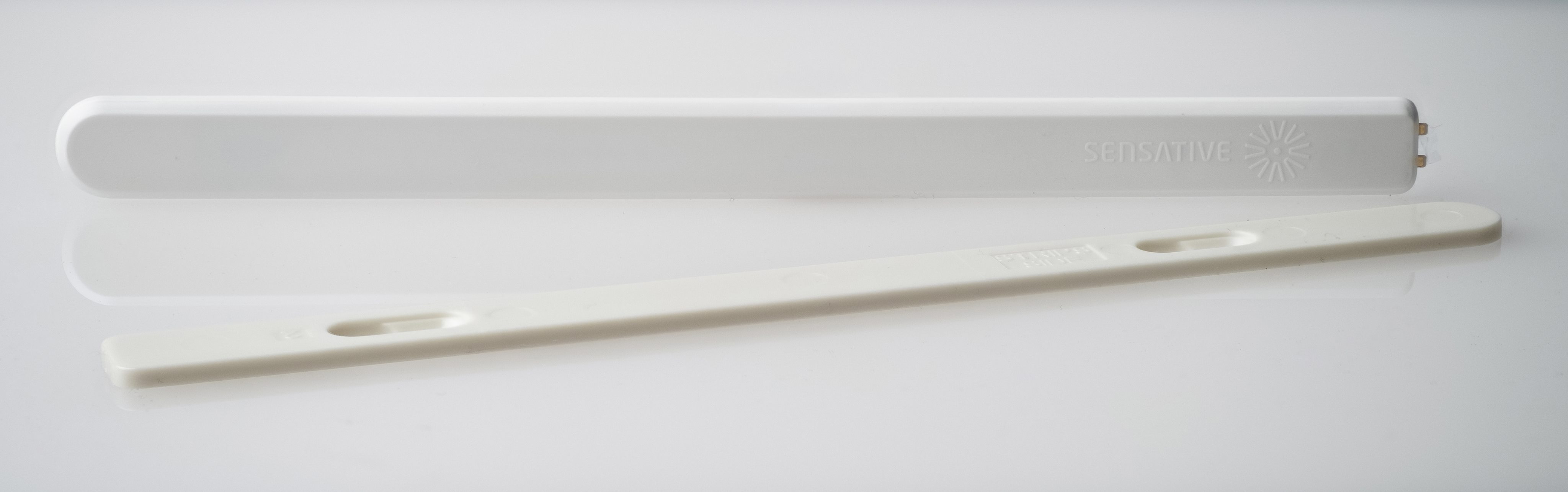
Strips Comfort 700/800 for Z-Wave Plus™
Strips benefits:
- Invisible or discreet design (< 3mm)
- No maintenance (up to 10 years)
- Long-range (100 m direct)
- Simple installation
- Encrypted communication
- Up to 10 years battery life
Strips for Z-Wave™ can be operated in any Z-Wave™ network with other Z-Wave™ certified devices from other manufacturers. All mains operated devices within the network will act as an extender, to increase the reliability of the network.
Strips Comfort 700/800 for Z-Wave™
Meet the ultra-slim comfort sensor for Z-Wave™ 700/800 series:
- Temperature sensor
- Humidity sensor
- Light (LUX) sensor
- On/Off switch
- Indoor use
- Discreet mounting
- Easy set up & installation
- Long-lasting battery (up to 10 years)
- SmartStart & S2 Security
- Z-Wave™ 700/800 extended range (up to 100 m range)
Strips Comfort 700 model numbers:
- Strips Comfort 700 (EU Retail pack): 11 02 021_1
- Strips Comfort 700 (US Retail pack): 11 02 022_1
- Strips Comfort 700 (EU Installer pack): 11 02 021_19
- Strips Comfort 700 (US Installer pack): 11 02 022_19
Strips Comfort 800 model names:
- Strips Comfort 800 (EU Retail pack) 11 02 031_1
- Strips Comfort 800 (US / US Long-Range Retail pack) 11 02 032_1
- Strips Comfort 800 (EU Retail pack) 11 02 031_19
- Strips Comfort 800 (US / US Long-Range Retail pack) 11 02 032_19
Strips Comfort 700/800 is the wireless humidity, temperature and light (LUX) sensor that gives you an excellent insight into your indoor environment, whether it be in your home, apartment, office or any other building. With Strips sliding button you can now also control lights, ventilation, shades and other IoT devices in your smart home or apartment.
Strips comes with Smart Start to reduce the time for installation for service providers, installers and end-users. It comes with a longer range of up to 100 meters (+150% compared with 500 series), increased security and even longer battery lifetime than before. Add these highly accurate functionalities for a greater comfort and energy efficiency without adding complexity. Connected to your Z-Wave™ system you can control indoor climate, turn off lighting, raise your blinds, activate ceiling fans, turn off your AC system, etc - there is a multitude of possibilities. Besides providing the data to keep your space in optimal climate conditions, they will also enable you to save money on energy expenses that are likely to make a big difference in your budget.
Whether your interest is in smart home applications or IoT applications for businesses, using Z-Wave™ Strips sensors brings a wealth of valued features such as ultra-slim discreet form factor and low power consumption for extended battery life (up to 10 years). For more information including product sheets, manuals, and tutorials, visit our products page."
Strips +Switch (Sliding button)
+Switch use-cases:
• Turn on/off lights
• Turn on/off heating/radiator
• Switch between home & away mode
• Initiate a rule (e.g. email notification)
Find more information about user cases here
+Switch adds a button to Strips sensors for controlling IoT devices and scenarios. The +Switch is the latest Strips accessory that adds a button functionality to Strips. It is compatible with all Strips LoRaWAN sensors and (coming) Strips Comfort 700/800 Z-Wave™.
By simply switching Switch you can control lights and other IoT devices, but also initiate predefined scenarios in your smart home or buildings and order services on demand.
Strips Comfort 700/800 Command classes
| Command Class | Version | Required Security Class |
|---|---|---|
| APPLICATION STATUS | 1 | None |
| ASSOCIATION | 2 | Highest granted Security Class |
| ASSOCIATION GROUP INFO | 3 | Highest granted Security Class |
| BATTERY | 1 | Highest granted Security Class |
| CENTRAL SCENE | 3 | Highest granted Security Class |
| CONFIGURATION | 4 | Highest granted Security Class |
| DEVICE RESET LOCALLY | 1 | Highest granted Security Class |
| FIRMWARE UPDATE MD | 5 | Highest granted Security Class |
| INDICATOR | 3 | Highest granted Security Class |
| MANUFACTURER SPECIFIC | 2 | Highest granted Security Class |
| MULTI CHANNEL ASSOCIATION | 3 | Highest granted Security Class |
| NOTIFICATION | 8 | Highest granted Security Class |
| POWERLEVEL | 1 | Highest granted Security Class |
| SECURITY 2 | 1 | None |
| SENSOR MULTILEVEL | 11 | Highest granted Security Class |
| SUPERVISION | 1 | None |
| TRANSPORT SERVICE | 2 | None |
| VERSION | 3 | Highest granted Security Class |
| WAKE UP | 2 | Highest granted Security Class |
| ZWAVEPLUS INFO | 2 | None |
Add Strips Comfort 700/800 to your Z-Wave™ Controller
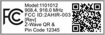
Comfort is a SmartStart enabled product and can be added to a Z-Wave™ network by using SmartStart. Start by scanning the Z-Wave™ QR Code present on the back label of the Strips, or on the DSK leaflet present in the box. Strips can be added to both secure and non-secure controllers and with or without SmartStart.
*US and Canada users can also add Strips as Long Range secure with SmartStart. Your device supports Long Range only if it has the following logo on the product box and Strips
Add Strips Comfort 700/800 using SmartStart inclusion
You can use this method of inclusion only if your Z-Wave™ Controller supports SmartStart.
- Open your Z-Wave™ Controller’s app and select SmartStart pairing.
- Scan the QR Code (You can find the QR Code on the back of Strips or in the package).
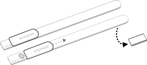
- Move +Switch towards the centre and remove the magnet from the back of Strips. (See picture below).
- One long LED blink means that Strips has been successfully added to your Z-Wave™ network.
SmartStart will automatically begin after 30 seconds and Strips will be added within 10 minutes if activated within the Z-Wave™ Controller range.
Note:
- Once the device is in SmartStart mode and not paired, it will attempt pairing with SmartStart for the first 15 mins, and thereafter every 3.5 hrs for a period of a month.
- If SmartStart fails pairing the first time, Strips will restart SmartStart. If it fails again, the device will reset.
- If none of the above is successful, you need to perform a manual wake-up to start SmartStart.
- In order to cancel SmartStart mode, the user can perform a Factory Default Reset
Add Strips Comfort 700/800 using classic inclusion (Non SmartStart Controllers)
-
Open your Z-Wave™ Controller’s application and start pairing mode.
-
Move +Switch towards the centre and remove the magnet from Strips (If you have previously removed the magnet from Strips, or need to re-add the device, performing a manual wake up will join the device when the controller is in pairing mode).
-
One long LED blink means that Strips has been successfully added to your Z-Wave™ network.
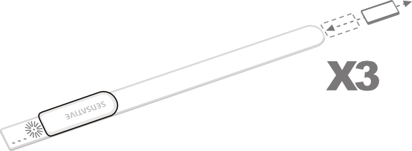
To perform a manual wake up (video):
- Take the magnet, move it to the rounded edge and wait for the blink. Then move the magnet away.
- Repeat this 3 times. A final short blink will confirm that the user command was successful.
Strips and radio communication
Strips uses low power radio signals to communicate with your Z-Wave™ controller. For best results, please consider the following:
Strips should not be mounted directly on metal, magnetic surfaces or encased within a metal structure as the range will reduced. Strips’ range is up to 100 meters. (325 feet) Any non-battery Z-Wave™ device will act as an extender to increase network reliability and range.
Poor network reliability will affect Strips’ battery life. To make sure that you have a good network, place Strips at its intended location and perform a Wake Up (see below). If Strips blinks 5 times, this indicates that Strips failed to communicate with the controller. If it happens you may move the Z-Wave™ controller closer or add an extender between the controller and Strips sensor.
To perform a manual wake up:
- Take the magnet, move it to the rounded edge and wait for the blink. Then move the magnet away.
- Repeat this 3 times. A final short blink will confirm that the user command was successful.
Test Strips has been included to your Z-Wave™ controller
Make sure Strips Comfort 700/800 is connected to your controller
To make sure that Strips is connected to your network:
Once added to your network, Strips will send a temperature, light (LUX), humidity report after one minute after a completed inclusion. Make sure that Strips status is updated in your Z-Wave controller.
Mounting Strips
Mounting Strips Comfort 700/800
Mounting Strips Comfort 700/800 using adhesives
Strips Comfort has an adhesive backing which can be used to mount Strips. Please make sure the surface is clean, dry and at least +10°C (+50°F). Remove the protective tape from Strips and place Strips firmly on a surface.
Note* Strips adhesive is permanent and may damage your Strips or the surface upon removal. If you need to remove Strips make sure to follow the necessary steps found here.
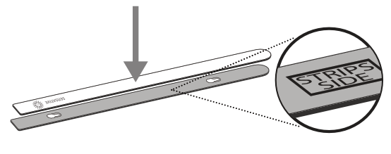
Mounting Strips Comfort 700/800 using the mounting plate
See the plate to mark the holes, and use the screws to mount the mounting plate. Remove the protective tape from Strips’ adhesive. Mount Strips Comfort on the marked “Strips Side” of the mounting plate as illustrated below.
Removing Strips from its mounted position
To easily remove Strips when the sensor is mounted with the adhesive backing, simply get floss or something similar, and gently draw it behind the back of the device and the surface it is mounted on and run the string up or down the length of the Strip, removing it from the surface.
Comfort 700/800 Configuration table
LED
| No | Name | Description | Values | Default |
|---|---|---|---|---|
| 2 | LED alarm event reporting (1 byte) | Turn On or Off LED for specific event indications (ex. alarms) | 0: Off 1: On, but no LED indication for associated nodes (1/5 blinks) 2: On with LED indications based on success/fail for BOTH the gateway and the associated nodes | 1 |
Temperature and humidity reporting
| No | Name | Description | Values | Default |
|---|---|---|---|---|
| 4 | Temperature and humidity reporting (1 byte) | Select temperature and humidity sensor reporting | 0: Off 1 = On. Sends temperature/humidity based on difference from last reported value (set in config parameters 26 and 28) 2: On. Periodic reporting of the actual temperature and the actual humidity value (set time in config parameter 25) 3: On. Periodic reporting of the average temperature value between reports. Will also send the actual humidity value (set time in config parameter 25) | 1 |
| 5 | Temperature unit (1 byte) | Select the temperature unit | 0: Celsius 1 = Fahrenheit | 0: (Except US frequency ) 1: (US frequency) |
| 6 | Temperature alarms (1 byte) | Turn On or Off temperature alarms (The alarms are not affected by parameters 4, 25 or 26) | 0: Off 1: On | 0 (Off) |
| 7 | High temperature alarm level (2 bytes) | Select high temperature alarm level | -20 to +80 (degree C), -4 to +176 (degree F) | 40 C or 104 F (US frequency) |
| 8 | Low temperature alarm level (2 bytes) | Select low temperature alarm level | -20 to +60 (degree C), -4 to +140 (degree F) | 5 C Or 41 F (US frequency) |
| 25 | Temperature and humidity reporting time (Activated in config parameter 4) (2 bytes) | Select the number of minutes between reports (15 mins to 24 hrs) | 15-1440: Minutes between reports (periodic reporting) | 60 |
| 26 | Temperature change for next report (Activated in config parameter 4) (1 byte) | Temperature must change by this value for a new report | 5 - 100, Input value converted to one decimal place [= 0.5 to 10.0 (degree C/F)] | 20 ( = 2.0 C) or 30 (=3 F) |
| 28 | Humidity change for next report (1 byte). Humidity reporting is activated in config parameter 4 | Humidity must change by this value for a new report | 2 to 10 (%) | 5 (%) |
Ambient light
| No | Name | Description | Values | Default |
|---|---|---|---|---|
| 9 | Ambient light reporting (1 byte) | Ambient light report settings. Using a filter (low-pass) is highly recommended to avoid large amounts of reports in fluctuating lights. | 0:Off 1: On without any filter. Not recommended. May cause large amounts of reports affecting the battery life 2-8: On. Uses a filter to filter out light fluctuations. The strongest filter is number 8. Recommended for most users | 8 |
| 10 | High ambient light (LUX) level trigger (4 bytes) | The sensor will send a light report when the light rises above this level. Can be used in scenarios to trigger other devices. When enabling parameter 10, parameter 11 must also be set with a lower value, else the trigger stays off | 20 - 64000 (LUX) 0: Off | 0 (Off) |
| 11 | Low ambient light (LUX) level trigger (4 bytes) | The sensor will send a light report when the light goes below this level. Can be used in scenarios to trigger other devices. When enabling parameter 11, parameter 10 must also be set with a greater value, else the trigger stays off | 10 - 42000 (LUX) 0: Off | 0 (Off) |
Slider Switch
| No | Name | Description | Values | Default |
|---|---|---|---|---|
| 29 | Slider switch function (1 byte) | Select if the switch should act as a binary switch or a timed switch | 1. Binary Switch 2. Timed Switch | 1 |
| 30 | Timed switch duration (1 byte) | Select the duration that should trigger the opposite state of the Switch (if 2 is selected in config parameter 29) | 1-60 (minutes) | 5 |
Z-Wave™ Command Class
| No | Name | Description | Values | Default |
|---|---|---|---|---|
| 31 | Use Multi-Command encapsulation (1 byte) | Send temperature and humidity sensor value reports and or temperature alarms related reports (Notification Report + Multi-Level Sensor Report + Central Scene Notification) in one message, this saves battery power. Make sure your gateway supports Multi-Command Command Class first | 0: Off 1: On | 0 (Off) |
| 32 | Use Central Scene Notifications (1 byte) | Central Scene Notifications are sent for the slider switch state change, high and low temperature alarms and high and low ambient light states. Scenes could be configured in the gateway. Scenes allow multiple devices to be controlled by a single Z-Wave™ command | 0: Off 1: On | 1 (On) |
Associations
| No | Name | Description | Values | Default |
|---|---|---|---|---|
| 33 | Basic Set value sent to Association group 3 when the slider switch is on (1 byte) | This config parameter defines the value sent to the devices in the Association group 3 (using Basic Command Class) | 0 - 255 | 255 |
| 34 | Basic Set value sent to Association group 3 when the slider switch is off (1 byte) | This config parameter defines the value sent to the devices in the Association group 3 (using Basic Command Class) | 0 - 255 | 0 |
| 35 | Thermostat mode for Association group 4 when the slider switch is on (1 byte) | This config parameter defines the value sent to the devices in the Association group 4 (using Thermostat Mode Command Class). Refer the Thermostat modes supported by the associated node | 1 - 13 | 1 |
| 36 | Basic Set value sent to Association group 6 on high temperature alarm (1 byte) | This config parameter defines the value sent to the devices in the Association group 6 (using Basic Command Class) | 0 - 255 | 0 |
| 37 | Basic Set value sent to Association group 6 on low temperature alarm (1 byte) | This config parameter defines the value sent to the devices in the Association group 6 (using Basic Command Class) | 0 - 255 | 255 |
| 38 | Basic Set value sent to the Association group 7 on high ambient light level report (1 byte) | This config parameter defines the value sent to the devices in the Association group 7 (using Basic Command Class) | 0 - 255 | 255 |
| 39 | Basic Set value sent to the Association group 7 on low ambient light level report (1 byte) | This config parameter defines the value sent to the devices in the Association group 7 (using Basic Command Class) | 0 - 255 | 0 |
Strips Comfort 700/800 Notifications events
| Notification Type | Notification Event | Information |
|---|---|---|
| Heat Alarm (04) | Clear Notification (00) | When other 2 events below are cleared |
| Heat Alarm (04) | Overheat detected (02) | Strips will send Heat Alarm when temperature rises above the set value in configuration parameter no.7 |
| Heat Alarm (04) | Under heat detected (06) | Strips will send Heat Alarm when temperature falls below the set value in configuration parameter no.8 |
| Home Security (07) | Clear Notification (00) | When other event (11) is cleared |
| Home Security (07) | Magnetic Field Interference Detected Event (11) | Strips will send a tamper alert if it detects that someone tries to wake up or manipulate Strips. |
Strips Comfort 700/800 Product identity
| Indicator ID | Description | Appearance and use |
|---|---|---|
| 80 (0x50) | Node Identify | The LED indicator is used to identify the node. |
Strips Comfort 700/800 Central scene
| Event | Scene | Key Attribute |
|---|---|---|
| +Switch: Slider switch on | Scene 1 | Key Pressed (00) |
| +Switch: Slider switch off | Scene 2 | Key Pressed (00) |
| High ambient light (LUX) level trigger | Scene 3 | Key Pressed (00) |
| Low ambient light (LUX) level trigger | Scene 4 | Key Pressed (00) |
| High temperature alarm | Scene 5 | Key Pressed (00) |
| Low temperature alarm | Scene 6 | Key Pressed (00) |
Strips Comfort 700/800 Associations
| Group | Name | Maximum no. of devices | Commands | Information |
|---|---|---|---|---|
| 1 | Lifeline | 1 | Notification Report Battery Report Multilevel Sensor Report Central Scene Notification Device Reset Locally Notification Indicator Report Multi-Command Encapsulation Command | The Lifeline group includes all signals that are sent automatically to keep a central controller notified of the status of Strips Comfort 700/800. These includes the battery level, the temperature, humidity and light lux levels, the central scene, high and low temperature and magnet detection tamper notifications. |
Strips +Switch
| Group | Name | Maximum no. of devices | Commands | Information |
|---|---|---|---|---|
| 2 | Binary Switch | 5 | Binary Switch Set | OFF – 00 (0x00) ON – 255 (0xFF) This association shall work for both Binary Switch and Timed Switch functions set in configuration parameter 29 – Slider switch function |
| 3 | Basic Set for Binary Switch | 5 | Basic Set | OFF – 00 (0x00) ON – 255 (0xFF) Values could be modified using the configuration parameters 33 & 34 This association shall work for both Binary Switch and Timed Switch functions set in configuration parameter 29 – Slider switch function |
| 4 | Thermostat Mode Set for Binary Switch | 5 | Thermostat Mode Set | Pre-requisite: configuration parameter no. 29 – Slider switch function set to 1 (Binary Switch) OFF – 00 (0x00) or The value set in the configuration parameter 35, Default is Heat Mode On – 01 (0x01) |
Temperature Alarms
| Group | Name | Maximum no. of devices | Commands | Information |
|---|---|---|---|---|
| 5 | Temperature Report for Temperature Alarms | 5 | Multilevel Sensor Report | Temperature Value |
| 6 | Basic Set for Temperature Alarms | 5 | Basic Set | High temperature alarm = OFF – 00 (0x00) Low temperature alarm = ON – 255 (0xFF) Values could be modified using the configuration parameters 36 & 37 |
Ambient light (LUX) level trigger
| Group | Name | Maximum no. of devices | Commands | Information |
|---|---|---|---|---|
| 7 | Basic Set for Ambient Light Report Levels | 5 | Basic Set | High ambient light (LUX) level trigger = ON – 255 (0xFF) Low ambient light (LUX) level trigger = OFF – 00 (0x00) Values could be modified using the configuration parameters 38 & 39 |
User commands
Wake Up
To wake up Strips manually for communication with the Z-Wave™ controller:
- Take the magnet, move it to the rounded edge and wait for the blink. Then move the magnet away.
- Repeat this 3 times in total. A final short blink will confirm that the user command was successful.
Add/Remove Strips
Place the controller into pairing or remove mode and perform the "wake up" pattern.
Factory Default Reset
You may need to reset Strips if your Z-Wave™ controller is missing or not responding. Follow the instructions for Wake Up, but on the 3rd repetition, keep the magnet at the rounded edge for 10 seconds. A long LED signal indicates success.
Tamper
Strips will send a tamper alert if it detects that someone tries to wake up or manipulate Strips.
LED notifications
How do to a LED Blink test:
1 Short LED Blink
- User feedback during commands
- Successfully sent report
- The notification when Strips is added to a network
2 Short LED Blink
The notification when Strips is not added to a network.
1 Long LED Blink
A user command is successfully executed.
5 Short LED Blinks
Error (e.g. communication with controller failed).
Important Information
- After removing magnets from the device, do not package it with magnets still attached.
- The drivers meant for 700-series Strips work seamlessly with the 800-series as well. Devices falling under the 800-series might be recognized as 700-series.
- When exposed to temperatures below room temperature, such as when the device is placed in a fridge or freezer, the battery may display lower levels that do not accurately represent its true charge.
Documentations - Links
Please find more documentation online: