Strips Guard 700/800 for Z-Wave Plus™
Strips benefits:
- Invisible or discreet design (< 3mm)
- No maintenance (up to 10 years)
- Long-range (100 m direct)
- Simple installation
- Encrypted communication
- Up to 10 years battery life
Strips for Z-Wave™ can be operated in any Z-Wave™ network with other Z-Wave™ certified devices from other manufacturers. All mains operated devices within the network will act as an extender, to increase the reliability of the network.
Strips Guard 700/800 for Z-Wave™
Meet Strips Guard 700/800 for Z-Wave™:
- Magnetic open/close sensor
- Discreet
- Weatherproof for in- and outdoor use
- Easy to set up & installation
- Long-lasting battery (up to 10 years battery)
- SmartStart & S2 security
- Z-Wave™ 700/800 extended range (up to 100 m range)
Strips Guard 700 model names:
- Strips Guard 700 (EU Retail pack): 11 01 021_1
- Strips Guard 700 (US Retail pack): 11 01 022_1
- Strips Guard 700 (EU Installer pack): 11 01 021_19
- Strips Guard 700 (US Installer pack): 11 01 022_19
Strips Guard 800 model names:
- Strips Guard 800 (EU Retail pack) 11 01 031_1
- Strips Guard 800 (US / US Long-Range Retail pack) 11 01 032_1
- Strips Guard 800 (EU Retail pack) 11 01 031_19
- Strips Guard 800 (US / US Long-Range Retail pack) 11 01 032_19
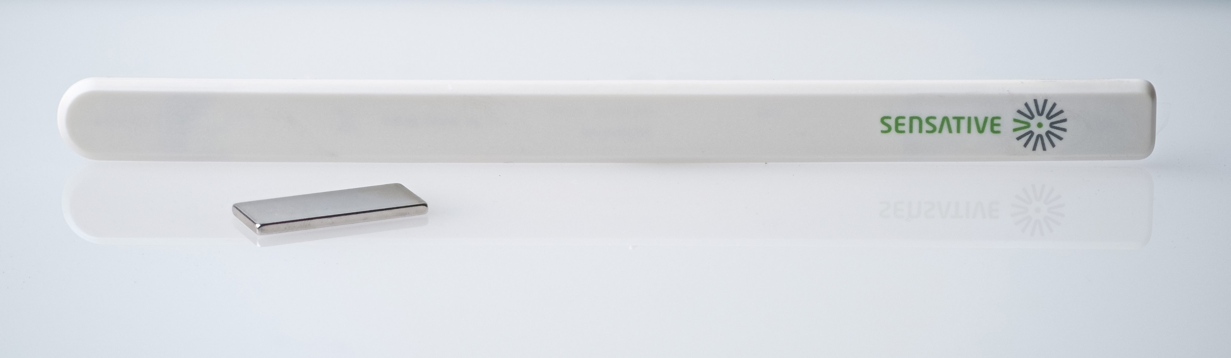
Strips Guard 700/800 is the game-changing magnetic sensor which in real-time monitors open/closed status changes in doors, windows, gates and similar. Suitable for both in- and outdoor applications.
Strips comes with SmartStart to reduce the time for installation for service providers, installers and end-users. It comes with a longer range of up to 100 meters (+150% compared with 500 series), increased security and even longer battery lifetime than before.
Creativity is the only limitation when it comes to discerning Smart Home & apartments applications. The sensor’s ultra-thin design (3mm) makes it perfect for mounting in narrow spaces where you can hide the sensors for functional, security, and esthetic reasons. Thanks to the enabling design, these magnetic sensors are also very suitable for monitoring the presence of paintings, sculptures and other valuables, or signal when a drawer is opened. Employ our sensors and let your smart home or apartment system keep track of all windows & doors, to inform you of any status changes real-time, and create automation directly through an app on your mobile device.
Whether your interest is in smart home applications or IoT applications for businesses, using Z-Wave™ Strips sensors brings a wealth of valued features such as ultra-slim discreet form factor and low power consumption for extended battery life (up to 10 years). For more information including product sheets, manuals and tutorials, visit our products page.
If you are looking for IoT applications that require a longer range, or you have a need for sensors with more functionalities per sensor type, we highly recommend you to take a look at our LoRaWAN products here, which are developed with business applications in mind.
Strips Guard 700/800 Command classes
| Command Class | Version | Required Security Class |
|---|---|---|
| APPLICATION STATUS | 1 | None |
| ASSOCIATION | 2 | Highest granted Security Class |
| ASSOCIATION GROUP INFO | 3 | Highest granted Security Class |
| BATTERY | 1 | Highest granted Security Class |
| CONFIGURATION | 4 | Highest granted Security Class |
| DEVICE RESET LOCALLY | 1 | Highest granted Security Class |
| FIRMWARE UPDATE MD | 5 | Highest granted Security Class |
| INDICATOR | 3 | Highest granted Security Class |
| MANUFACTURER SPECIFIC | 2 | Highest granted Security Class |
| MULTI CHANNEL ASSOCIATION | 3 | Highest granted Security Class |
| NOTIFICATION | 8 | Highest granted Security Class |
| POWERLEVEL | 1 | Highest granted Security Class |
| SECURITY 2 | 1 | None |
| SENSOR BINARY | 1 | Highest granted Security Class |
| SUPERVISION | 1 | None |
| TRANSPORT SERVICE | 2 | None |
| VERSION | 3 | Highest granted Security Class |
| WAKE UP | 2 | Highest granted Security Class |
| ZWAVEPLUS INFO | 2 | None |
Add Strips Guard 700/800 to your Z-Wave™ Controller
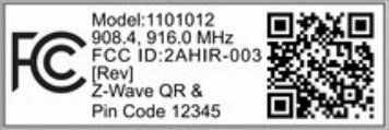
Guard 700/800-series is a SmartStart enabled product and can be added to a Z-Wave™ network by using SmartStart. Start by scanning the Z-Wave™ QR Code present on the back label of the Strips, or on the DSK leaflet present in the box. Strips can be added to both secure and non-secure controllers and with or without SmartStart.
*US and Canada users can also add Strips as Long Range secure with SmartStart. Your device supports Long Range only if it has the following logo on the product box and Strips
Add Strips Guard 700/800 using SmartStart pairing
You can use this method of inclusion only if your Z-Wave™ Controller supports SmartStart.
- Open your Z-Wave™ Controller’s app and select SmartStart pairing.
- Scan the QR Code (You can find the QR Code on the back of Strips or in the package).
- Remove the magnets from Strips (If you have previously removed the magnets from Strips, or need to re-add the device, performing a manual wake up will join the device when the controller is in pairing mode).
SmartStart will automatically begin 30 seconds after removing the magnets and Strips will be added within 10 minutes when it has been activated within the Z-Wave™ Controller range.
One long LED blink means Strips has been successfully added to your Z-Wave™ network.
Note:
- Once the device is in SmartStart mode and not paired, it will attempt pairing with SmartStart for the first 15 mins, and thereafter every 3.5 hrs for a period of a month.
- If SmartStart fails pairing the first time, Strips will restart SmartStart. If it fails again, the device will reset.
- If none of the above is successful, you need to perform a manual wake-up to start SmartStart.
- In order to cancel SmartStart mode, the user can perform a Factory Default Reset
Add Strips Guard 700/800 using classic inclusion (Non SmartStart Controllers)
- Open your Z-Wave™ Controller application and start pairing mode.
- Remove the magnets from Strips (If you have previously removed the magnets from Strips, or need to re-add the device, performing a manual wake up will join the device when the controller is in pairing mode).
- One long LED blink means Strips has been successfully added to your Z-Wave™ network.
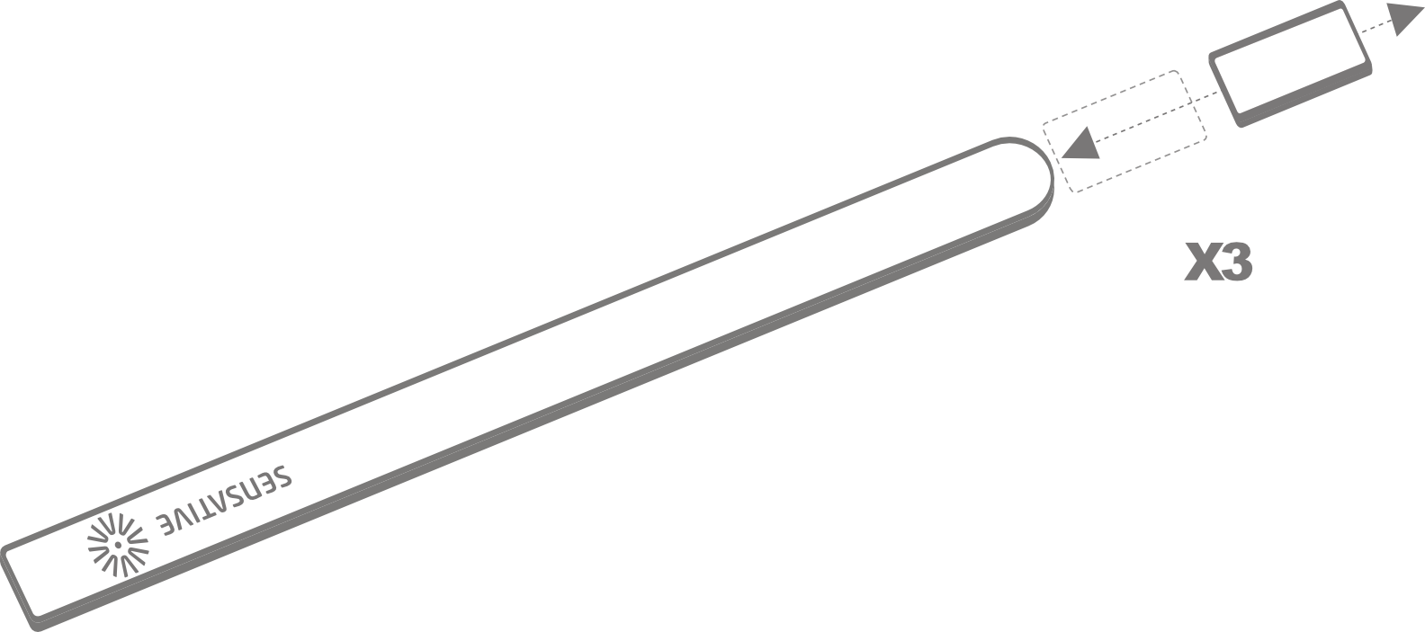
To perform a manual wake up (video):
- Take the magnet, move it to the rounded edge and wait for the blink. Then move the magnet away.
- Repeat this 3 times. A final short blink will confirm that the user command was successful.
Strips and radio communication
Strips uses low power radio signals to communicate with your Z-Wave™ controller. For best results, please consider the following:
Strips should not be mounted directly on metal, magnetic surfaces or encased within a metal structure as the range will reduced. Strips’ range is up to 100 meters. (325 feet) Any non-battery Z-Wave™ device will act as an extender to increase network reliability and range.
Poor network reliability will affect Strips’ battery life. To make sure that you have a good network, place Strips at its intended location and perform a Wake Up (see below). If Strips blinks 5 times, this indicates that Strips failed to communicate with the controller. If it happens you may move the Z-Wave™ controller closer or add an extender between the controller and Strips sensor.
To perform a manual wake up:
- Take the magnet, move it to the rounded edge and wait for the blink. Then move the magnet away.
- Repeat this 3 times. A final short blink will confirm that the user command was successful.
Test Strips has been included to your Z-Wave™ controller
Make sure Strips Guard 700/800 is connected to your controller
To verify Strips is working properly:
Move the squared magnet towards the square edge as shown in the picture. Check that your Z-Wave™ Controller displays the status correctly.

If your Z-Wave™ system doesn’t respond, you may need to change Strips’ notification type from the controller.
Mounting Strips
Mounting Strips Guard 700/800
Pre-installation
When its time to install Strips, depending on your application, some measurements/alignments could be needed before permanent mounting with our adhesive backing.
To correctly mount Strips, please follow the steps below:
- Make sure the surface is clean, dry and at least +10°C(+50°F). Use the included cloth to clean and prepare the surfaces.
- Remove the brown protective film from the small Strips test adhesive. This adhesive is used before the final placement so it is easy to re-position Strips if needed.
- Place Strips where you want it mounted. Check the position by carefully closing the door/window and then opening it completely again.
- Identify where the magnet should be placed (See picture below). Remove the protective film and place the magnet. Close and open again to validate that your Z-Wave™ controller detected the changes. Re-position if needed.
- Check that the door/window can be fully closed and opened and that your Z-Wave™ controller detects the changes.
- When you are satisfied, mark the exact position for Strips. Remove it from its position, remove the long film protecting the adhesive backing and place Strips exactly as you marked.
- Keep the spare magnet; it can be used to wake up, remove or reset Strips in the future.
First mark an area to install the sensor, then remove the brown pre-mounting tape on the back of the device:
Tip: Using regular tape also works great.
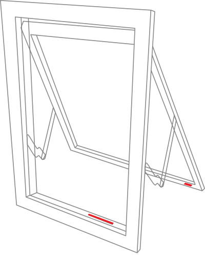
For good functionality in the door or window:
- To place Strips invisibly, you need a gap in your door or window frame with a minimum height of 3.5 mm.
- Strips may be mounted on the frame (recommended) and the magnet on the door/window, or vice versa.
- Open the door/window fully to check that the placement of Strips and the magnet does not interfere with hinges or locking mechanisms.
Magnet placement and sensor range:
Check that the magnet can be placed so that it is less than 10 mm from Strips’ square end when the door/window is closed. When the door/window is open, the magnet should be at least 30 mm away from Strips.

Permanent Mounting
Once the desired measurements/markings have been applied, its time to mount Strips in its final location. This step is easy as cleaning the application area, then removing the adhesive backing on Strips.
Removing Strips from its mounted position
To easily remove Strips when the sensor is mounted with the adhesive backing, simply get floss or something similar, and gently draw it behind the back of the device and the surface it is mounted on and run the string up or down the length of the Strip, removing it from the surface.
Guard 700/800 Configuration table
| No | Name | Description | Size | Values | Default |
|---|---|---|---|---|---|
| 1 | Notification type | Select the notification type for the door and window open or close events | 1 byte | 0: Binary sensor report + Notification report (Access Control) 1: Notification report (Access Control) 2: Notification report (Home Security) | 1 |
| 2 | LED alarm event reporting | Turn On or Off LED for specific event indications (ex. alarms) | 1 byte | 0: Turns off LED for door open events 1:On | 1 |
| 15 | Activate supervision | Activate Supervision command for only important alarm events or all events (Supervised commands require a confirmation from the gateway when a notification is received) | 1 byte | 0:Events sent with S2 Encapsulation only 1: Only Door Open Alarm Report (Events sent with S2 and supervision encapsulation) 2: Unsolicited reports (Door Open/Close,Tamper clear, Wake-up notification and Battery Report events sent with S2 and supervision encapsulation) | 1 |
| 22 | Advanced configuration | Enables advanced configurations | 1 byte | 0: Standard (Forces parameter behavior as follows: #1=1, #15=1, #16=10000, #17=Sensative standard (Retries with an incrementally longer period until reconnected), #18=0, #19=Off 1: Enable advanced parameters 16-19, #1=2, #15=2) | 0 |
The below configurations are only used if parameter 22 is set to 1 (Advanced configuration)
Parameters 16-19, 22 are categorized as ”Advanced Settings”
| No | Name | Description | Size | Values | Default |
|---|---|---|---|---|---|
| 16 | Supervision wait time | The number of milliseconds to wait for a Supervision response when a Supervised message is sent | 2 bytes | 500 - 30000 (ms) | 10000 (ms) |
| 17 | No. of failed event retries | Number of retries when a confirmation is not received | 1 byte | 0-5 | 1 |
| 18 | Failed event retry interval | The minimum number of seconds between retries | 1 byte | Min = 1 second, Max = 60 seconds | 6 (seconds) |
| 19 | Heartbeat interval | Number of minutes between periodic battery reports (Heartbeats) | 1 byte | 5-70 (mins) Accepts multiples of 5 mins Any arbitrary value in between 5 and 70 will be rounded up to a multiple of5 | 70 (mins) |
Strips Guard 700/800 Notifications events
| Notification Type | Notification Event | Information |
|---|---|---|
| Access Control (06) | Door Open (22) | When Configuration Parameter 1 = 0 or 1. Notification Type (Access Control) |
| Access Control (06) | Door Close (23) | When Configuration Parameter 1 = 0 or 1. Notification Type (Access Control) |
| Home Security (07) | Clear Notification (00) | When other 2 events below are cleared |
| Home Security (07) | Intrusion Unknown Event (02) (Door Open) | When Configuration Parameter 1 = 2. Notification Type (Home Security) |
| Home Security (07) | Magnetic Field Interference Detected Event (11) | Strips will send a tamper alert if it detects that someone tries to wake up or manipulate Strips. |
| System (09) | Software Failure with Manufacturer Proprietary Failure Code (04) | In case of software failure the device shall reboot and send out this notification event |
Strips Guard 700/800 Product identity
| Indicator ID | Description | Appearance and use |
|---|---|---|
| 80 (0x50) | Node Identify | The LED indicator is used to identify the node. |
Strips Guard 700/800 Associations
| Group | Name | Maximum no. of devices | Commands | Information |
|---|---|---|---|---|
| 1 | Lifeline | 1 | Notification Report Battery Report Sensory Binary Report Device Reset Locally Notification Indicator Report | The Lifeline group includes all signals that are sent automatically to keep a central controller notified of the status of Strips Guard 700/800. These includes the battery level, Door open/close and magnet detection tamper notifications. |
User commands
Wake Up
To wake up Strips manually for communication with the Z-Wave™ controller:
- Take the magnet, move it to the rounded edge and wait for the blink. Then move the magnet away.
- Repeat this 3 times in total. A final short blink will confirm that the user command was successful.
Add/Remove Strips
Place the controller into pairing or remove mode and perform the "wake up" pattern.
Factory Default Reset
You may need to reset Strips if your Z-Wave™ controller is missing or not responding. Follow the instructions for Wake Up, but on the 3rd repetition, keep the magnet at the rounded edge for 10 seconds. A long LED signal indicates success.
Tamper
Strips will send a tamper alert if it detects that someone tries to wake up or manipulate Strips.
LED notifications
How do to a LED Blink test:
1 Short LED Blink
- User feedback during commands
- Successfully sent report
- The notification when Strips is added to a network
2 Short LED Blink
The notification when Strips is not added to a network.
1 Long LED Blink
A user command is successfully executed.
5 Short LED Blinks
Error (e.g. communication with controller failed).
Important Information
- After removing magnets from the device, do not package it with magnets still attached.
- The drivers meant for 700-series Strips work seamlessly with the 800-series as well. Devices falling under the 800-series might be recognized as 700-series.
- When exposed to temperatures below room temperature, such as when the device is placed in a fridge or freezer, the battery may display lower levels that do not accurately represent its true charge.
Documentations - Links
Please find more documentation online: