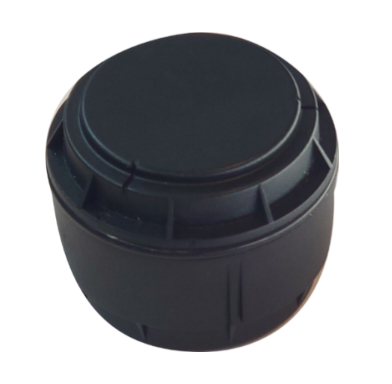
Puck Radar
Description
Puck Radar is an exceptionally versatile, ultra-low power radar sensor designed for LoRaWAN. It's well-suited for a multitude of applications, including detecting presence, measuring distance to objects, and determining levels in tanks, as well as assessing snow depth.
It captures the intensity of the radar signal reflected from various distances, processes the data, and reports the findings based on set parameters. Puck Radar comes equipped with multiple methods tailored for common scenarios adaptable for a broad range of applications such as parking, waste management, silo & septic tank levels, distance metering, seat occupancy or snow level metering.
Puck Radar sensor can be ordered with two different housings, supporting different user needs. Puck Radar Standard lens housing: The radar will detect objects/levels within an approx. +/- 60 ° angle. Puck Radar Narrow lens housing: The radar will detect objects/levels within an approx. +/- 30 ° angle.
Benefits & Use Cases
The compact cylindrical format, weather resistance (IP67), long battery life, LoRaWAN long range connectivity, up to 6.8 m radar range and mm accuracy open a wide range of applications for Puck Radar including:
- Parking space occupancy: Preferably installed 10-300 cm above the ground, either in front of or above a parking spot.
- Distance/Level Metering: Monitoring containers, silos, wells, trash bins, septic tanks, cesspits, water levels & more.
- Snow Level Meter: Provides accurate, reliable readings under various environmental conditions.
- Seat Occupancy detection: Efficiently determines the occupancy status of seats or desks.
Several predefined methods for operating the radar and analyzing the results are included as standard in Puck Radar. Each method can be configured for different use case specifics.
Radar method description
The Puck Radar offers a suite of pre-defined and customizable radar techniques suited for various applications, detailed as follows:
Closest Object Detection
This method pinpoints the nearest object that reflects a signal surpassing a preset amplitude threshold within a defined measurement range.
Farthest Object Detection
It identifies the most distant object exceeding a specific reflection amplitude threshold, also within a predetermined measurement range.
Largest Reflection Detection
This technique detects the object that produces the most significant reflection echo within the designated measurement distance.
These techniques are versatile, catering to diverse use cases supported by the methods below.
Parking Monitoring
Technique Used: Largest Reflection Detection
Functionality: Identifies objects within a specified distance, indicating the occupancy status (occupied/unoccupied), along with the distance and echo amplitude from the detected object. While particularly useful for parking monitoring, this technique is also applicable for level detection in user scenarios where the strongest echo likely indicates the level in container or tank.
Battery Life: Tailored for up to 10-year battery lifespan with a sensor scan interval of 30 seconds for parking use cases, and extendable beyond 10 years for user scenarios permitting longer scan intervals.
Well Level Measurement
Technique Used: Farthest Object Detection
Functionality: Accurately measures the distance to the water level in a well and the amplitude of the radar echo, ideal for use cases where the most distant echo above the amplitude threshold represents the level to be measured.
Battery Life: Designed to last up to 10 years of battery life with a 10-minute sensor scan cycle.
Garbage Bin Fill Level
Technique Used: Closest Object Detection
Functionality: Offers adjustable sensitivity to either detect or ignore lightweight material close to the sensor, providing both distance and echo amplitude data.
Battery Life: Designed to last up to 10 years with a scanning interval of every 10 minutes.
Seat Occupancy Detection
Technique Used: Closest Object Detection
Functionality: Efficiently measures and reports occupancy status.
Battery Life: Achieves up to 7 years of battery life with a 30-second scanning interval.
These methods provide a comprehensive overview of the Puck Radar's capabilities, demonstrating its adaptability across various use cases and emphasizing operational efficiency alongside extended battery life.
Noise Reduction and Customizable Settings
To further enhance performance and tailor Puck Radar to different measurement environments, noise, and unwanted signals from moving objects can be reduced through averaging. This helps to stabilize measurement results and improves the reliability of detected signals. Users can also customize the measurement range, sensitivity, and threshold settings to fine-tune the radar's response based on specific needs and environmental conditions. These adjustable options allow for a tailored configuration that optimizes both accuracy and efficiency for each unique use case.
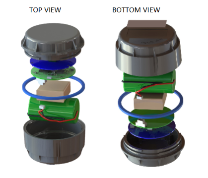
Figure 1: Explode view of Puck Radar with standard lens
Puck Radar's housing is composed of two plastic components, complemented by a rubber O-ring for enhanced sealing. The device features a user-replaceable battery, with additional batteries available for purchase separately.
Puck Radar is available in two versions. Puck Radar Standard lens with an approx. +/- 60° radar width suitable for applications covering a wider area. Puck Radar Narrow lens with an approx. +/- 30° radar width suitable for applications where a more focused radar beam is better suited.
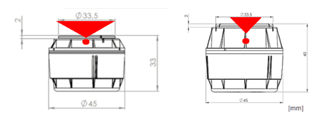
Figure 2: Puck Radar housings with Standard (left) & Narrow (right) lense. Actual radar sensor marked witha red dot and a red triangle indicating the radar beam width
Software
Puck Radar from Sensative is equipped with a sophisticated software architecture that includes a Virtual Sensing Machine (VSM) embedded in its firmware. This VSM executes specialized sensor applications designed for the device's sensing capabilities and specific use cases.
For more specialized requirements, Sensative provides tailored application and radar method development through its expert engineering services. This customization enables Puck Radar to be precisely adapted to meet unique needs, thereby significantly enhancing its performance in a variety of specialized settings.
Getting started
Initial Setup & Activation (OTAA)
Pre-Activation Steps:
- Prior to activating the device, ensure it is registered on the designated LoRaWAN server.
- Utilize the Dev EUI and Network Key provided with your digital delivery information for registration.
Activation:
- Following registration, briefly bring any NFC reader close to the device to initiate activation. Most mobile phones are equipped to serve as NFC readers.
- The activation process might take up to two minutes. Successful join activity will be indicated on the LoRaWAN Network Server.
- The device will continuously attempt the activation process until it successfully connects to the registered LoRaWAN network. Joining the network might take up to 24 hours once the LoRaWAN network becomes available.
Installation
Effectiveness of the Puck Radar sensor would be compromised by dirt, water, or any physical barriers in its path. Choose a mounting location that minimizes these obstructions. As a wireless device, Puck Radar should not be encased or shielded by metal, as this will impact its wireless range.
Adhesive
The provided adhesive is suitable for attaching the device to smooth, dry surfaces such as metal or plastic. Avoid applying the adhesive on oily or cold surfaces (below 5°C). For optimal adhesion, clean the surfaces with a mixture of isopropyl alcohol (IPA) and water (about 50% to 70% IPA) before using the adhesive.
Mounting Plates
For enhanced installation flexibility, the device is compatible with an optional mounting plate that accommodates both screw and cable tie attachments. This accessory allows for versatile positioning, enabling the plate to be securely attached to either the back or front of the device using the provided yellow adhesive. It is important to correctly position the Puck at the center of the plate for optimal functionality. The design of this mounting system ensures a secure and convenient installation in various locations and orientations, adapting seamlessly to the unique needs of your application.
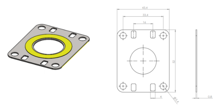
Figure 3: Puck Mounting plate with mounted adhesive.
Flush Mounting
Puck Radar can also be discreetly integrated into walls or ceilings through flush mounting. This requires a 45 mm diameter hole for the sensor, ensuring an unobtrusive and aesthetically appealing installation. Note that battery replacement may be challenging with flush-mounted devices.
Step-by-Step flush mounting installation:
- Selecting the Location: Identify a clear area that aligns with your monitoring objectives. The sensor should be oriented correctly to direct the radar beam towards the target.
- Drilling the Hole: Drill a 45 mm diameter hole at the chosen spot. Ensure the hole is clean and free of debris.
- Installing the Sensor: Apply a thick layer of sealant at the bottom of the drilled hole. Place the sensor with its back (label side) downwards in the hole, ensuring it remains correctly positioned while the sealant sets. Avoid applying glue or sealant on the sensor's lid to ease future battery replacements. Remember that any glue or sealant on the top of the radar lid could affect the sensor's performance.
- Adding a Cover Plate: For aesthetic purposes, a plastic cover plate can be installed to conceal the sensor. The cover plate should not contain glass, metal, or carbon as it will significantly reduce the radar performance and range. It may be wise to verify that the radar performance before a cover plate is permanently installed. The mounting plate in figure 3 can also be used.
Operations
As the Puck Radar device accumulates operational time, you may find opportunities to enhance its reporting accuracy or battery efficiency. The device can be configured to best suit your specific use case while ensuring prolonged battery life.
Key configuration options include:
- Radar Method: Choose from Well, Bin, Parking, or Seating, each tailored for specific scenarios. Detailed descriptions of these methods are provided below.
- Radar Measurement Cycle: Adjusting the cycle length can extend battery life. Longer cycles lead to less frequent measurements but improved battery longevity.
- Radar Range: Configure the starting point and length of the radar's range. This customization can improve measurement accuracy and conserve battery power.
- Number of Radar Pulses per Measurement: This setting is crucial for detecting stationary objects in challenging environments, such as in streaming water. Note that increasing the number of pulses may decrease battery life.
- Radar Sensitivity or Threshold: Adjust the radar's sensitivity and/or threshold to balance between detection accuracy and potential false triggers.
- Sensor Reporting Type: Choose between periodic reporting or reporting based on value or state changes. This selection depends on your need for real-time data versus battery conservation.
- Configuration of other built-in sensors: Tailor the settings to align with your specific requirements.
Battery replacement
To access the battery, rotate the lid counterclockwise; to close and secure it after maintenance, rotate it clockwise for about a quarter turn. It's vital to replace and correctly install both the rubber cushion and the O-ring to ensure the device's optimal functionality and waterproof integrity.
Use a Star tool at each end of the Puck Radar to apply the necessary torque for fully tightening the lid, thus maintaining its waterproof seal.
For comprehensive maintenance, battery replacement kits are available. These kits include replacement batteries, Star tools, new O-rings, and rubber cushions to ensure a complete and proper maintenance process.
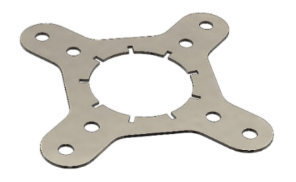
Figure 4: Star tool
Never try to open or close the Puck Radar housing with any other tools as you may destroy the housing or fail to correctly close the unit.
Miscellaneous
When deploying the Puck Radar in diverse use cases and environments, several factors should be taken into account for optimal performance:
- Radar Beam: The radar sensor detects objects within a beam lob of ±60°, reaching up to 6.8 meters. In many applications, using a narrow lens to reduce the radar lob to ±30° can be advantageous to minimize false echoes.
- Physical Environment: It's crucial to carefully consider the sensor's mounting location. Assess if modifications to the physical environment can help reduce unwanted radar echoes from surrounding objects.
- Radar Reflection: Different materials reflect radar waves differently. Dense materials like metal, glass, and water are strong reflectors. Conversely, materials such as paper, plastics, cloth, and human tissue offer weaker reflections but are still detectable by the radar sensor. The size and shape of the reflecting object also influence the amplitude of the reflected signal. Larger, flat, and orthogonal surfaces reflect more radar waves than smaller, uneven, or tilted surfaces.
- Signal Averaging: Averaging the radar signal can help reduce noise in measurements or mitigate the influence of moving objects. Increasing the number of samples in each radar burst can enhance sensitivity, particularly if the target object remains stationary during measurement. However, if the target object is in motion (like streaming water, human tissue, or a fluttering object), reducing the number of averaging samples may be more effective.
Each of these considerations plays a crucial role in the successful deployment and operation of the Puck Radar, ensuring accurate measurements and reliable performance in a variety of settings.
More information
- Default Puck Radar application documentation incl configuration options
- Link to Acconeer radar sensor XM122
- Link to Acconeer housing CA-122
- Manual for the radar module in Puck Radar 2.8.0 Rev 1.0.1 (PDF)
- PUCK Settings Specification 1.5.2 (PDF) (For devices produced before 2025)
- VSM Config Tool
- Support
- Support resource center
- Android app (coming soon)
Technical information
| Specification | Description |
|---|---|
| Features | 60 GHz pulsed coherent radar sensor. Cloud-supported geo-positioning Temperature sensor (Typical accuracy: +/- 2 °C at 0-30 ° C) LPWAN connectivity: LoRaWAN Near field connectivity: NFC |
| Radar specifications | Acconeer XM122 radar module 60.5 GHz EIRP: Max +10 dBm 0.3 - 6.8 m range with cm precision |
| LoRaWAN specifications | Regions: * EU (863-870 MHz) * US915 (902-928 MHz) * AS923-1 (920-923 MHz) * AS923-2 (923-925 MHz) * KR (923-925 MHz) * AU (915-928 MHz) * IN (865-867 MHz) Up to +14 dBm output power Up to 10 km range LoRaWAN v1.0.4 OTAA (Over The Air Activation & Configuration) A-OTA (Upgrade Application Over The Air) Multiple LoRaWAN network keys for sensor-initiated roaming |
| 2.4 GHz protocol specifications | 2.4 GHz (2.4 -2.483 GHz) Data rate: 2 Mbps Max output power: 5.5 dBm Sensitivity: -101 dBm (Long range) |
| Geo-positioning specifications | The device supports the following geo-positioning services: - 2.4 GHz WIFI (b/g/n) MAC address scanning - LoRa TDoA (Time Difference on Arrival) A geo-solving cloud service is required for geo-positioning. |
| Dimensions | Puck Radar Std Puck Radar Narrow Diameter: 45 mm 45 mm Height: 30 mm 45 mm Weight incl battery: 38 g 43 g Radar beam (approx.): +/- 60° +/- 30° Radar Reference Point (RRP): 1.1 cm 2.6 cm The distance is measured from the radar RRP located 1.1/2.6 cm below the front of Puck. |
| Operating conditions | -30 to + 80° C Weather protected: IP67 Rubber ring sealing Circuit boards moisture protected by conformal coating |
| Storage conditions | +10 to + 30° C |
| Power supply | Replaceable 2.1 Ah Li-SOCl2 battery. 3.6 V |
| Battery life | 5-10 years battery life using default settings and hourly LoRaWAN (SF 9 or better). |
| NFC | 13.56 MHz Range: 2 cm. Position your NFC enabled phone on the front side of Puck radar such that the phone NFC antenna is centered just above the Puck radar sensor. Optional Android app for local configuration and data monitoring (password protected). |
| Other | * The device features battery voltage level monitoring capability. A voltage reading below 2.8 V (when the temperature exceeds +10°C) indicates that the battery should be replaced. * Data memory for off-line storage of time-stamped data. |
Safety & Compliance
Puck Radar is equipped with a replaceable primary Li-SOCl2 (Lithium Thionyl Chloride) battery. It is important to dispose of this battery responsibly, following recycling guidelines for batteries.
When managing Li-SOCl2 batteries, it's imperative to proceed with caution due to their sensitivity. Ensure to avoid short-circuiting, puncturing, or subjecting them to high temperatures. It is especially crucial to prevent exposure to temperatures above +80°C to safeguard both your safety and the battery's optimal performance longevity. Additionally, refrain from detaching the battery connector or severing the battery wire to maintain the battery's integrity and functionality.
Note: This equipment has been tested and found to comply with the limits for a Class B digital device, pursuant to part 15 of the FCC Rules. These limits are designed to provide reasonable protection against harmful interference in a residential installation. This equipment generates, uses and can radiate radio frequency energy and, if not installed and used in accordance with the instructions, may cause harmful interference to radio communications. However, there is no guarantee that interference will not occur in a particular installation. If this equipment does cause harmful interference to radio or television reception, which can be determined by turning the equipment off and on, the user is encouraged to try to correct the interference by one or more of the following measures:
- Reorient or relocate the receiving antenna.
- Increase the separation between the equipment and receiver.
- Connect the equipment into an outlet on a circuit different from that to which the receiver is connected.
- Consult the dealer or an experienced radio/TV technician for help
FCC NOTICE (for USA):
This device complies with Part 15 of the FCC Rules. Operation is subject to the following two conditions: (1) this device may not cause harmful interference, and (2) this device must accept any interference received, including interference that may cause undesired operation. Federal Communication Commission (FCC) Radiation Exposure Statement: This equipment complies with FCC radiation exposure limits set forth for an uncontrolled environment. In order to avoid the possibility of exceeding the FCC radio frequency exposure limits, human proximity to the antenna shall not be less than 20cm (8 inches) during normal operation. The antenna(s) used for this transmitter must not be co-located or operating in conjunction with any other antenna or transmitter. No changes shall be made to the equipment without the Company’s permission as this may void the user’s authority to operate the equipment.
INDUSTRY CANADA STATEMENTS:
This device complies with Industry Canada licence exempt RSS standard(s). Operation is subject to the following two conditions: (1) this device may not cause interference, and (2) this device must accept any interference, including interference that may cause undesired operation of the device. This equipment complies with the safety requirements for RF exposure in accordance with RSS-102 §2.5.2. This equipment must be installed and operated in accordance with the provided instructions and a minimum 20 cm spacing must be provided between the antenna and any person’s body during wireless modes of operation.
INDUSTRY CANADA STATEMENTS:
Cet appareil est conforme avec Industrie Canada exempt de licence Rss standard(s). Son fonctionnement est soumis aux deux conditions suivantes : (1) cet appareil ne peut causer d’interférences, et (2) cet appareil doit accepter toute interférence, y compris des interférences qui peuvent provoquer un fonctionnement indésirable du périphérique. Ce dispositife est conforme à la norme de sécurité en matière d’exposition RF conformé-ment à la RSS-102 §2.5.2. Ce dispositif doit être installé et utilisé conformément aux instructions fournies et à 20 cm espacement minimal doit être prévu entre l’antenne et le corps de toute personne pendant les modes sans fil de fonctionnement.
INDUSTRY CANADA NOTICE
“This device complies with ISED’s licence-exempt RSSs. Operation is subject to the following two conditions: (1) This device may not cause interference; and (2) This device must accept any interference, including interference that may cause undesired operation of the device”